BMW E36 Blog

Replacing BMW E36 Brake Pads

26th December 2006

Replacing BMW E36 Brake Pads

Hi Guys,


I found this nice article ,which was written by Wayne R. Dempsey, on this page. I thought that many of you guys would like to know how to change these pads. For those who don’t like to use their hands, at least, it’s a nice thing to know how to do it.


I saw that many times being done, but there’s nothing better than doing the work yourself to make sure you learned it, so here you go … enjoy. Please remember to wash your hands after you’re done 🙂


Disclaimer
: Use it at your own risk!


Replacing your brake pads is one of the easiest jobs to perform on your BMW. In general, you should inspect your brake pads about every 10,000 miles, and replace them if the material lining of the pad is worn down enough to trigger the pad replacement sensor. In reality, most people don�t inspect their pads very often, and usually wait until they see the little brake warning lamp appear on the dashboard. It’s a wise idea to replace the pads, and inspect your discs as soon as you see that warning lamp.


     If you ignore the warning lamp, you may indeed get to the point of metal on metal contact, where the metal backing of the pads may be contacting the brake discs. Using the brakes during this condition will not only give you inadequate braking, but will also begin to wear grooves in your brake discs. Once the discs are grooved, they are damaged, and there is almost no way to repair them. Resurfacing will sometimes work, but often the groove cut will be deeper than is allowed by the BMW specifications. The smart thing to do is to replace your pads right away.


     Brake pads should only be replaced in pairs � replace both front pads or both rear pads at a time. The same rule applies to the brake discs that should be checked each time you replace your brake pads.


     The procedure for replacing pads on all the wheels is basically the same. There are slight configuration differences between front and rear brakes, but in general the procedure for replacement is similar. The first step is to jack up the car and remove the road wheel. This will expose the brake caliper that presses the pads against the disc


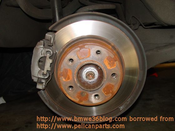
Tip: Make sure that the parking brake is off when you start to work on the pads.


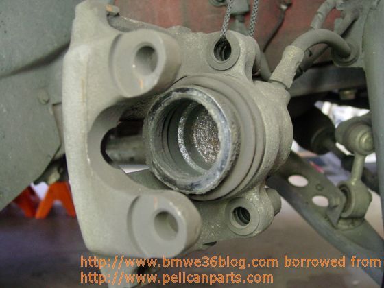
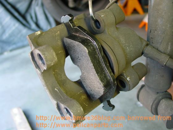
     If you look inside the caliper, you will see the brake pads – usually they will look very thin, as is shown here


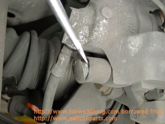
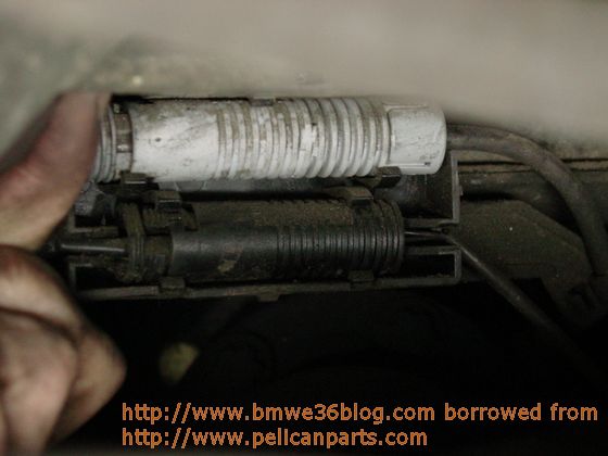
Begin by removing the small plastic cap that covers the caliper guide bolts


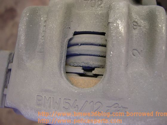
The BMW caliper used on the 3-Series (and many other BMWs) is a single piston caliper design. One piston presses against the side of the brake disc, and the whole caliper slides on the guide bolt to achieve equal pressure on the disc from both pads.


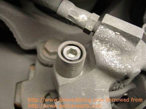
replace the brake pads, you need to remove the caliper. Remove both guide bolts from the
caliper


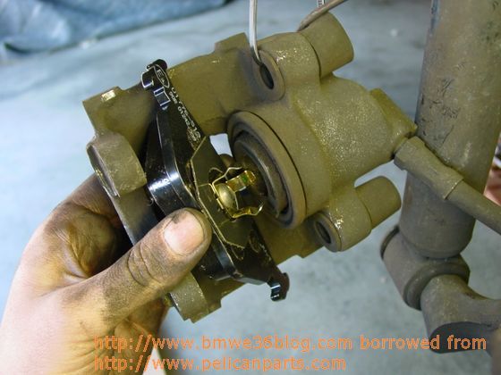
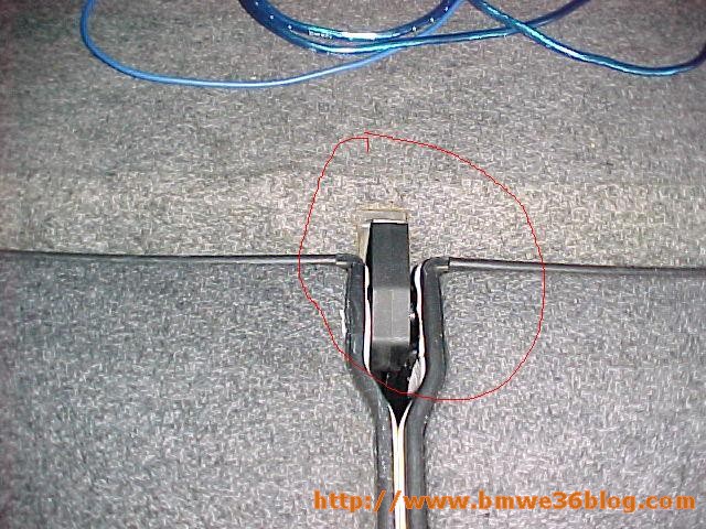
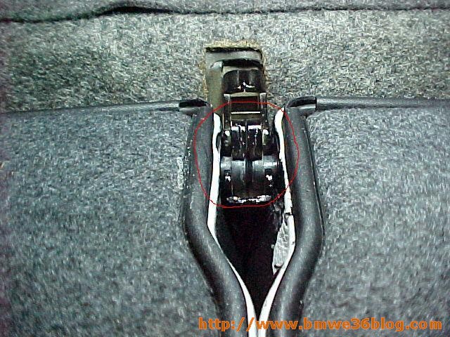
Then remove the brake pad retaining clip (keeps the pads from rattling)


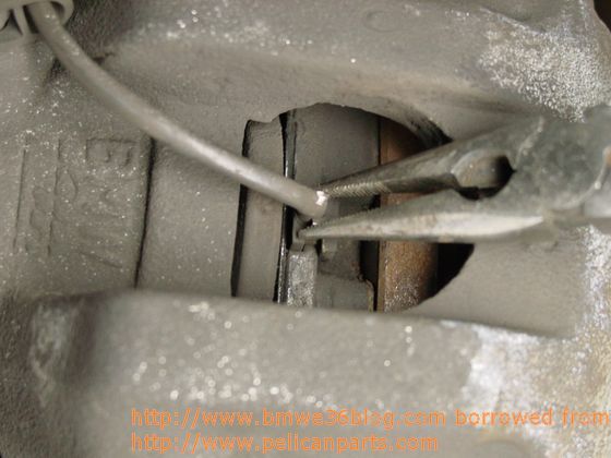
Make sure you wear safety glasses during this step, as the clip can come flying off if you’re not careful. Then, use a pair of needle-nose pliers to remove the brake pad sensor


After the guide bolts have been removed, you should be able to simply lift the caliper off of its mount


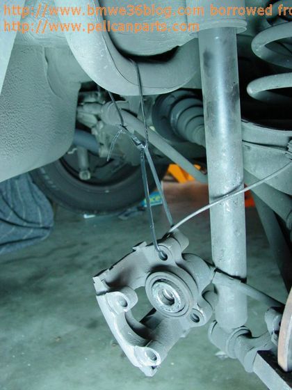
Suspend the caliper using some zip-ties or rope – don’t let the caliper hang from its rubber hose (very bad). See the follow screenshot for details.


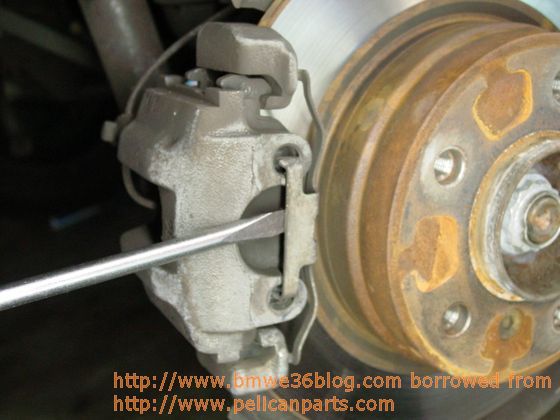
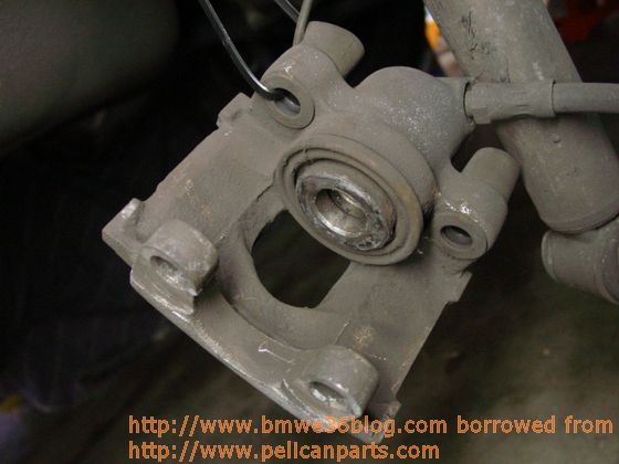
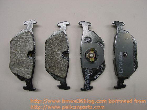
As this point, you can pluck the outer brake pad out of the caliper, and use a screwdriver to pry the inner pad out of the caliper piston. The caliper should resemble this when you’re done.


Once you have the pads removed, inspect the inside of the caliper. You should clean this area with some compressed air and isopropyl alcohol. Make sure that the dust boots and the clamping rings inside the caliper are not ripped or damaged. If they are, then the caliper may need to be rebuilt.


At this point, you should inspect the brake discs carefully. Using a micrometer, take a measurement of the disc thickness. If the disc is worn beyond its specifications, then it�s time to replace it along with the one on the other side. See our Pelican Technical Article on Replacing BMW Brake Discs for more information.


The installation of the new brake pads is quite easy. You will need to take a small piece of wood or plastic and push the caliper piston back into the caliper


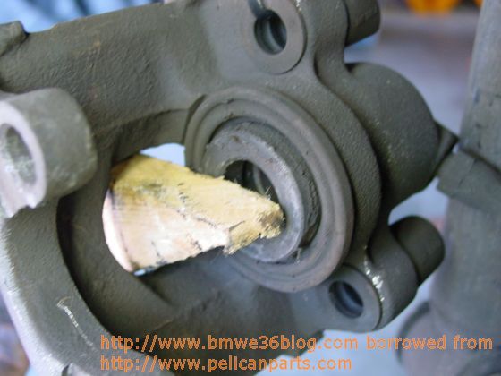
This is because the new pads are going to be quite a bit thicker than the old ones, and the piston is set in the old pad�s position. Pry back the piston using the wood, being careful not to use too much force. Using a screwdriver here can accidentally damage the dust boot and seals inside the caliper, and is not recommended. Be aware that as you push back the pistons in the calipers, you will cause the level of the brake reservoir to rise. Make sure that you don�t have too much fluid in your reservoir. If the level is high, you may have to siphon out a bit from the reservoir to prevent it from overflowing. Also make sure that you have the cap securely fastened to the top of reservoir. Failure to do this may result in brake fluid accidentally getting on your paint.


When the piston is pushed all the way back, you should then be able to insert the new pads


into the caliper. If you encounter resistance, double check to make sure that the inside of the caliper is clean.  Simply snap the inner brake pad into place using your hand


When firmly mounted, the new pad should resemble this


     The process for assembly is the reverse of the disassembly.  Mount the caliper back onto its mounting bracket, surrounding the brake disc.  If the caliper won’t fit, then you need to push in the piston a bit more until the space in-between both pads is wide enough for the brake disc to fit.  Tighten down the guide bolt using a torque wrench to 22 ft-lb (30 Nm).


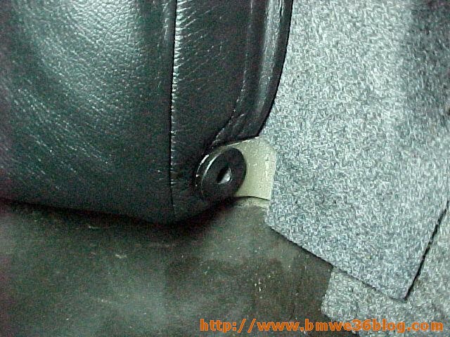
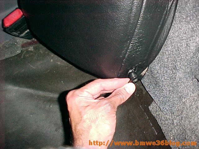
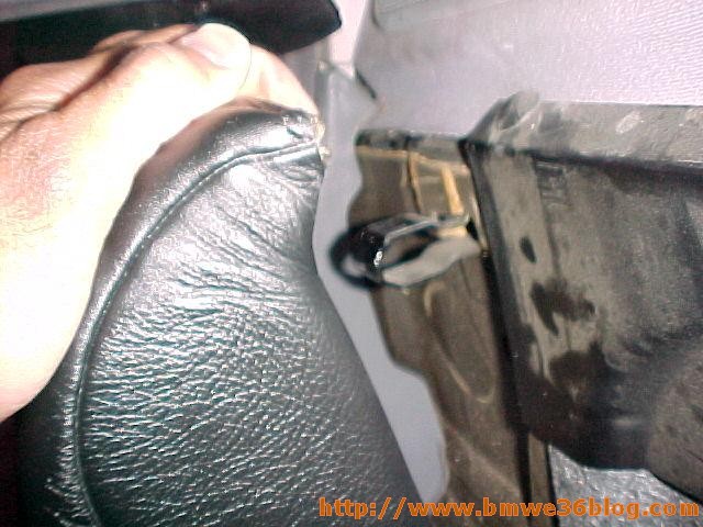
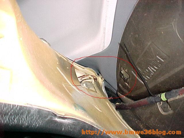
     If your brake sensors activated the lamp on your dashboard, they should be replaced with new ones.  Disconnect the sensor


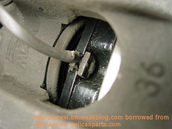
and plug in the new one.  Then snap the new sensor into the small gap in the brake pad


     You also may want to spray the back of the brake pads with some anti-squeal glue. This glue basically keeps the pads and the pistons glued together, and prevents noisy vibration. Anti-squeal pads can also be purchased as sheets that are peeled off and placed on the rear of the pads.

     When finished with both sides, press on the brake pedal repeatedly to make sure that the pads and the pistons seat properly. Also make sure that you top off the master cylinder brake fluid reservoir if necessary. Brake pads typically take between 100 and 200 miles to completely break in. It�s typical for braking performance to suffer slightly as the pads begin their wear-in period. Make sure that you avoid any heavy braking during this period.

     Well, there you have it – it’s really not too difficult at all. 


Are you looking for more do it yourself procedures (DIY) ? I recommend the Bentley BMW 3 series service manual for you. I got it and I think it’s a gold mine for us -BMW E36 Owners-. If you didn’t grab your copy yet, get it right now! I’m sure you’ll find this book worth every penny you’ve paid for. Get the Bentley BMW 3 series service manual


Wait for more from BMW E36 Blog


best regards,

Tony Sticks.

Want to receive exciting tips & information about BMW E36 cars? Enter your Email:-


posted in Brakes, Do It Yourself | 11 Comments

23rd December 2006

How to remove BMW E36 rear seats?

How to remove the rear seats that fold down. Come
over here Kid, Let me show you how to do this!?


First you pop the bottle and open up a Corona, then pop the bottom seat off by
pulling up and then out towards the front of the car. You have to pull on both
sides from the bottom portion of the seat up with both hands. (Pull it quick).
Once you have the bottom seat off, take a 16mm wrench or socket and take your
seat belts off. You then have to open both seats and bring them down. Once they
are down, in the center where the seats meat halfway you are going to see this.

Take a flat tip screwdriver and pry it off from the rear. When you take it off,
it�s going to look like this. You will see 2 latches, one for the left and one
for the right. All you have to do is push the latches to the rear and pull up on
the side that you want. (Look at picture below)

Once you lift up, pull the seat towards the opposite side, and it will come off
the other side and you will see this.

Take that bushing looking thing and pull it out. If it�s to hard, pry it out
with a flat tip screwdriver.

After taking that bushing portion thing out, Place your hand on the top portion
of the side and yank it out. It should look like this.

You then pull up on it and take it off the other little bracket it has on the
bottom. It will look like this. (Picture below).


That is it!! Same thing for the other side. Installation is the same way as
removal.?


Are you looking for more do it yourself procedures (DIY) ? I recommend the Bentley BMW 3 series service manual for you. I got it and I think it’s a gold mine for us -BMW E36 Owners-. If you didn’t grab your copy yet, get it right now! I’m sure you’ll find this book worth every penny you’ve paid for. Get the Bentley BMW 3 series service manual


Wait for more!


best regards,

Tony Sticks.


Want to receive exciting tips & information about BMW E36 cars? Enter your Email:-


posted in Do It Yourself, Interior | 3 Comments

21st December 2006

Installing Seat Heaters for BMW E36


Disclaimer: Use this info at your own risk!! I’m not responsible if this didn’t work for you :-).
Specialized knowledge is required.
Installation time is appox. 4-5 hours, though this may vary according to the condition of the vehicle and its fittings.

Information
All instructions and illustrations are given for left-hand drive models. Certain work steps must be carried out in mirror-image fashion for right-hand drive models.
The seat heating is ready for operation when the ignition key is turned to position 2 (terminal 15).
The seat cushion-heating conductors are marked R (right) and L (left).
The backrest-heating conductors can be installed on either side.

Tools and materials required
Regular screwdriver
Phillips screwdriver
Torx screwdriver T 20
1/2" Torque wrench
Ratchet with 1/2" drive
1/2" Extension
1/2" Drive socket, A/F 16mm
Ratchet with 1/4" drive
1/4" extension
1/4" drive socket, A/F 7mm, 10mm
Cable lamp
Universal pliers
Pointed pliers

Contents
1.Preliminary work
2.Overview of connectors at supplementary wiring harness
3.Installing supplementary wiring harness
4.Installing actuating switches
5.Installing heating conductors

1.Preliminary work
Print out fault memory (or memories)
Disconnect battery
Remove paneling at fool pedals
Remove paneling at bottom left-hand and right-hand speakers
Remove glove box
Remove center console
Remove driver and passenger seats
Remove right-hand and left-hand entrance strips
Remove right-hand and left-hand seat-belt fixtures

2. Overview of connections at supplementary wiring harness

F 36 62 262 M

3. Installing supplementary wiring harness

F 36 51 128 M


Remove metal hexagon screws (1) from distribution box fixture in left-hand footwell.


F 36 62 276 M

Remove cover of distribution box.
Remove Torx screws.


Pull upper section (1) of distribution box upwards as far as vehicle-wiring harness will allow.

F36 51 129 M

Remove guide element (1) of vehicle wiring harness in direction of arrow in illustration.


Installation information

In order to prevent moisture from penetrating distribution box, ensure that guide element (1) is installed correctly in distribution box.

F 36 64 112 M

Release lock (1) of fuse carrier (fuse F1 � F10) X10015 (2) in direction of arrow in illustration.

Remove Fuse carrier X10015 (2) in direction of arrow in illustration.


F 36 64 113 M

Remove lock (1) of fuse carrier X10015 (2) in direction of arrow in illustration.


F 36 62 265 M

Lay supplementary wiring harness along vehicle wiring harness as shown in illustration:
Lay branches a � d into distribution box (1),
Branches e � h to left-hand fan-connector box (2),
branch i to earth support X173 (3),
branches j and k to front-left seat (4),
branches l and m to center console (5) and
branches n and o to front-right seat (6).


F 36 64 114 M

a. Plug branch for output terminal, fuse F4 (1), red/violet cable, into plug-in station No. 8 of fuse carrier X10015 (2) in distribution box.
b. Plug branch for input terminal, fuse F4 (1), red cable, into pug-in station No. 7 of fuse carrier X10015 (2) in distribution box.


Install lock of fuse carrier X10015 (2).
Install fuse carrier X10015 (2).
Plug 15 Amp safety fuse into plug-in station F4 of fuse carrier X10015 (2).


F 36 62 283 M

c. Plug branch for terminal 30 (1), red cable, into fan connector X1066 (2), red cable, in distribution box.
d. Plug branch for terminal 15 (1), green/blue cable, into fan connector X1076 (3), green/blue cable, in distribution box.


F 36 62 263 M

e. Connect branch for relief relay socket X63, relay K9 (1), to pin base X63 (e) and connect to plug-in station (2) of left-hand fan-connector box (3).
f. Plug branch for fan connector X13021, red/yellow cable, into left-hand fan-connector box (3).
g/h. Plug branches for instrument light (5), grey/red cable, into fan connector X1019 (4), grey/red cable, of fan-connector box (3).

F36 51 256 M

i. Connect branch for earth brown cable, to earth support X173 (1) under instrument panel on left.


F 36 62 266 M

j/k. Lay branches for front-left seat, black 4-pin connectors X732 and X733, along vehicle wiring harness (as shown in illustration) through opening (1) in carpet to illustration point of front-left seat.
l/m. Lay branches for actuating switches, yellow 6-pin connectors X651 and X658, along vehicle wiring harness (as shown in illustration) to installation point in center console.
n/o. Lay branches for front-right seat, black 4-pin connectors X740 and X741, along vehicle wiring harness (as shown in illustration) through opening (1) in carpet to installation point of front-right seat.


4. Installing actuating switches

F 36 62 264 M

Note
In the case of vehicles with power windows, the openings have already been cut and it is only necessary to unclip the covers.
Cut out opening (2) of center console (1) as shown in illustration and press in cover frames.
Dimension A: 44mm
Dimension B: 24mm
Dimension C: 105mm
Install center console (1).
Lay branch l through left-hand opening and branch m through right-hand opening (2) and connect actuation switches S53 and S54.
Press actuating switches S53 and S54 into opening (2).


5.Installing heating conductors

F 36 51 258 M

Cut off split pins (1) on underside of seat.
Lift out seat cushion (2).

Installation information

Replace split pins (1) of seat cushion.

F 36 51 259 M

Sport seats only
Remove Torx screws (1).
Tilt backrest (2) in direction of arrow in illustration.

F 36 51 260 M

Lift out seat cushion (1).
Carefully lift out seat cover (2) from connecting strip (3).
Remove seat cushion (1).

F 36 62 284 M

All models
Release seat cover 91) from tensioning tabs (2).

F 36 51 262 M

Fold up seat cover 91) and remove retaining clips (2) of seat cushion.
Remove seat cover (1).

F 36 51 263 M

Note
Right-hand and left-hand heating conductors are marked accordingly.
Place corresponding heating conductor (1) on seat cushion (2) as shown in illustration.
Fit seat cover and secure with retaining clips.

F 36 62 289 M

Remove securing ring (1) and retaining clip (3).
Detach Bowden cable (2).
Secure bracket (4) (from installation kit) as shown in illustration.

F 36 62 293 M

Lever out clips (1).


F36 62 290 M

Pull out head restraint (1) in direction of arrow in illustration.
Remove lever (3), unclip cover (2) and remove Torx screws (4).
Remove cover (5).

F 36 62 291 M

Remove Torx screws (1) and detach backrest (2) in direction of arrow in illustration.

F 36 62 292 M

Release seat cover (1) from tensioning tabs (2).

F 36 62 285 M

Fold up backrest cover (1) and remove fastening clips (2). Remove backrest cover (1).

F 36 51 269 M

Place heating conductors (1) on backrest as shown in illustration.
Fit backrest cover (2) and secure with fastening clips.

F 36 51 270 M

Reinstall backrest 91) in reverse sequence to installation.
Lay cable (2) of backrest (1) and seat cushion (4) through opening (3) of seat base.
Install seat cushion (4).
Secure connectors (5 and 6) to bracket of seat base.

F 36 51 271 M

Plug branches j and k and n and o(1 and 2), black 4-pin connectors, into mating connectors of seat heating of left-hand/right-hand front seats.

Reinstall all removed parts in reverse sequence to removal.

Connect battery and test for correct operation.


Are you looking for more do it yourself procedures (DIY) ? I recommend the Bentley BMW 3 series service manual for you. I got it and I think it’s a gold mine for us -BMW E36 Owners-. If you didn’t grab your copy yet, get it right now! I’m sure you’ll find this book worth every penny you’ve paid for. Get the Bentley BMW 3 series service manual


Want to receive exciting tips & information about BMW E36 cars? Enter your Email:-


posted in Do It Yourself, Interior | 17 Comments