BMW E36 Blog

Installing immobiliser for your BMW E36 . . . DIY!

10th September 2007

Installing immobiliser for your BMW E36 . . . DIY!


For those of you who don’t know what an immobiliser is, it’s simply an electronic device that is designed to prevent cars from being hot wired and stolen easily. If a car has an immobiliser installed, this means that the thief will need hours and hours + very good knowledge about cars to be able to get that car to work, or he may simply choose to knock on your door and ask you to give him a hand to fix your car LOOOL 🙂 as he may think it’s not working and needs some fixing. For those of you who are looking to protect their cars from being stolen and care about their car safety, the answer is easy, install a car immobiliser.

I have found this post here which talks about the process of installing an immobiliser for your BMW E36, so I thought I’d post it here in order  for you guys to follow and protect your car. If you’re interested in getting a car immobiliser, you can take a look at this immobiliser on eBay.

For those of you who like to fix their BMW car(s) by themselves, I recommend you to get the Bentley BMW 3 series service manual which is one of the best books I’ve ever read. I got it and recommend you to get one for you as it will save you too much time and money while fixing your car.


Disclaimer: Use this info at your own risk!! I’m not responsible if this didn’t work for you :-).

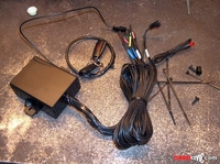
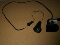
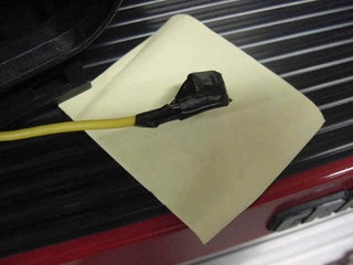
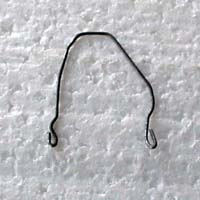
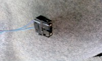
So you want to install immobiliser like this one? if you know how to solder wires then i think you will qualify

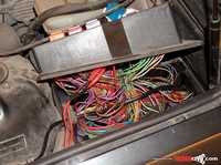
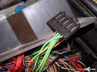
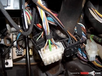
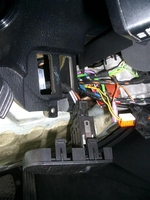
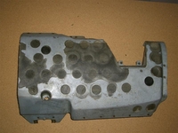
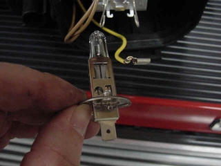
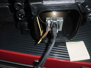
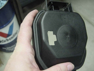
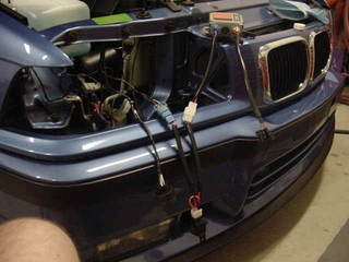
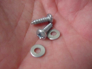
Step 1: Open up fuse box, you will want to make thieves life as hard as possible. You need torx screwdriver. Unscrew two front screws, be careful, apply pressure, do not break torx pattern on heads. Also open drivers side under dash to get access to wires and screws that hold fuse box in place. Unscrew these 4 screws to get fuse box loose

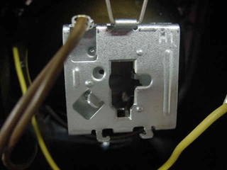
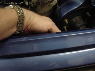
Now you can get access to fuse box rear screws. unscrew them carefully. open the box

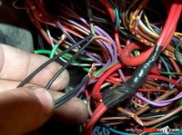
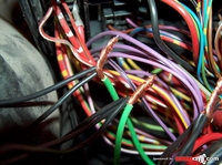
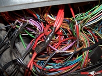
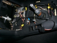
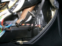
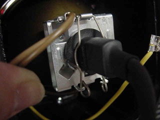
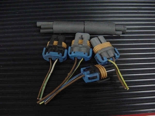
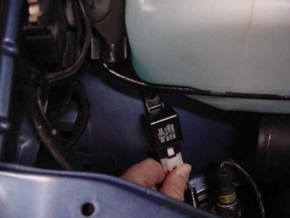
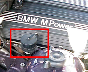
Step 2: Locate circuits that you will immobilise. For example, green/purple wire coming from fuel pump fuse (17)is ideal. Measure voltage on wire( test light or tester one lead grounded):
Ignition off – no voltage
Ignition on – no voltage
Crank and run – +12

When car running, cut the wire- if engine stops( after couple seconds ), you have found right one. You can connect it temporarily together to locate another circuit. Connect it to immobiliser as on its wiring diagram

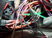
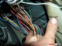
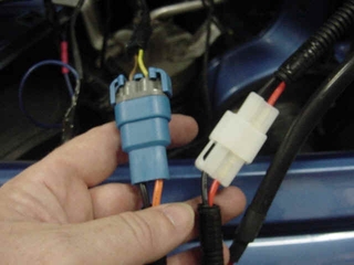
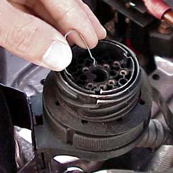
Second circuit can be ignition for ECU. It is green wire going from connection point to engine harness connector outside fuse box. It has power when ignition is on. If you cut it engine will stall immediately, remember that there are couple wires in that connector cut the right one, if you miss, connect back and be more careful next time

Step 3: Connect it to immobiliser wiring ( connect now fuel pump wire too )

remember power comes from ignition lock and goes to engine harness: twin wires for immobilising, third ignition sense for immobiliser

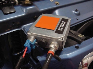
Step 4: Power up immobiliser (red permanent power, brown ground)

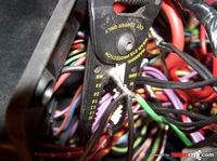
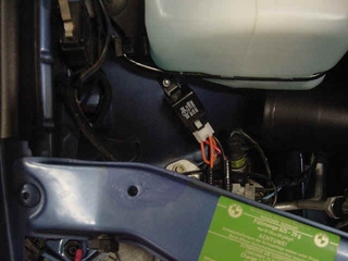
Step 5: Solder all wires

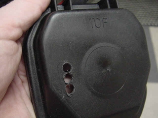
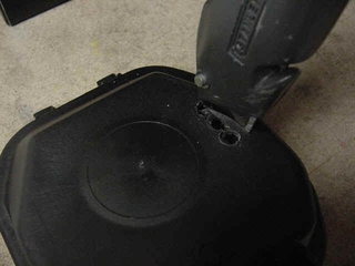
Step 6: Cut sharp edges

Step 7: Isolate all connections

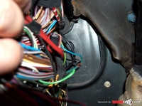
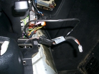
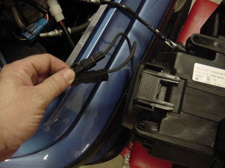
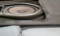
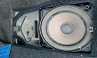
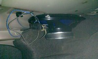
Step 8: Locate drivers side door switch wire near drivers side speaker (brown/gray/yellow).

Never connect immobiliser circuits on steering column. It is too easy to reconnect.

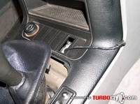
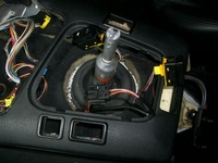
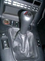
Step 9: Install LED and antenna into center console. antenna can be located anywhere where you want, it does not work through metal.

Step 10: Install led and antenna into center console. Antenna can be located anywhere where you want, it does not work through metal

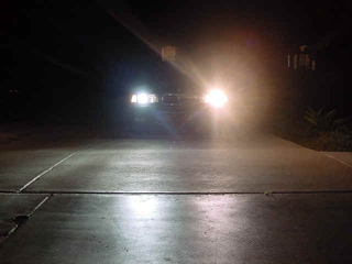
Step 11: You’re done! 🙂

Wiring Diagram:


Are you looking for more do it yourself procedures (DIY) ? I recommend the Bentley BMW 3 series service manual for you. I got it and I think it’s a gold mine for us -BMW E36 Owners-. If you didn’t grab your copy yet, get it right now! I’m sure you’ll find this book worth every penny you’ve paid for. Get the Bentley BMW 3 series service manual

BMW E36 Blog: The ultimate BMW E36 information source.


Want to receive exciting tips & information about BMW E36 cars? Enter your Email:-


posted in Do It Yourself, Electrical, Technical Info, Tips & Tricks | Comments Off on Installing immobiliser for your BMW E36 . . . DIY!

4th September 2007

Installing lighted shift knob for your BMW . . . DIY!


I always wanted to illuminate my BMW shift knob and I didn’t realize that it’s a straight forward job. I recall that I had to cut into my shift knob to do this to my BMW E30 before and the job was very hard to do and it didn’t look like I was expecting. Of course, that’s before I find out that there’s an illuminated shift knob that is ready to be installed. So, by getting this illuminated shift knob, the task became very easy. Take a look at the DIY below. It’s a straight forward task to do. I hope you like it

For those of you who like to fix their BMW car(s) by themselves, I recommend you to get the Bentley BMW 3 series service manual which is one of the best books I’ve ever read. I got it and recommend you to get one for you as it will save you too much time and money while fixing your car.

Disclaimer: Use this info at your own risk!! I’m not responsible if this didn’t work for you :-).

I have seen a lot of threads about lighted shift knobs and many suggestions on how to install it. What follows is the factory
intended retrofit option. (Although I am technically removing the wiring, it is the same for installation.)

Unscrew the Phillips head screw holding the dimmer console in place. The dimmer console is located to the left of the steering wheel. This console then easily pops out of the dash.

What you see connected to the back of it is the factory retro-fit wiring harness.

You want this wire to terminate in the shift console to be connected to your shift knob.

I ran this wire under the carpet with the other wires. This is what it would look like before tucking it under the carpet:

With a little slack the wires pull part way out of the dash back at the dimmer console:

Plugged into the back of the add on wiring harness is the standard wiring harness for the interior lights.

I ran the wires through the dash behind this:

You have to take off the under dash, driver’s side knee panel to get to this. It removes with a wratchet extension and an M10 socket.

With this piece removed you can see I ran the wire behind the factory wire strap to hold it in place. This opens simply by pulling out from the top.

In total it would look like this:

I think the entire deal, knob and wiring harness came shipped from pacific for under $100.

To gain access to the shifter area do the following:

Pull the shift knob up. This takes some force, don’t be worried but don’t hit yourself in the head either. The shift boot removes easily by pulling up on the sides at the corners. To remove the sunglass console you first have to remove the check computer (OBC). To do this reach your hand into the sunglass console and find the hole in the middle in the top. Press up to release the catch on the OBC and push it forward from the back. Then slide the sunglass console up and then rotate it out.

The driver’s side knee panel has three screws. One on either side of the steering wheel and one in the footwell on the center console side. This panel slides out with a little effort. Then you have to remove 3 bolts with a 10mm socket on the metal heat guard as described above. To remove the OBC refer to the cubby removal DIY in my sig. Here is the final install picture:

This is a screenshot of how it should look like when it’s done

You can get the illuminated shift knob from here. Just look for part #25 11 2 231 561 or #25 11 2 231 551


Are you looking for more do it yourself procedures (DIY) ? I recommend the Bentley BMW 3 series service manual for you. I got it and I think it’s a gold mine for us -BMW E36 Owners-. If you didn’t grab your copy yet, get it right now! I’m sure you’ll find this book worth every penny you’ve paid for. Get the Bentley BMW 3 series service manual

BMW E36 Blog: The ultimate BMW E36 information source.


Want to receive exciting tips & information about BMW E36 cars? Enter your Email:-


posted in Do It Yourself, Electrical, Interior, Technical Info, Tips & Tricks | 2 Comments

10th April 2007

How to Install HID inside your BMW E36 – DIY

Hi Friends,


I started to think recently about upgrading my car’s lights. So the obvious choice that came right to my mind is the HID lights installation. As usual, I started by looking at the articles which explain the process and how much it will cost (money $$$ and effort). I found a very good article which explains the process in too much details and it really made me feel like I will start on the project right away. It turned out to be very easy compared to what I had in mind. If you’re looking for a good HID kit, don’t go with the XenTec HID conversion kit H1 10000K Single Beam Xenon (sky blue). You can read all about it in my Xentec HID Review. Anyway, the article is below and I think it’s really great if you’re interested in doing the upgrade or at least to understand the process.


Disclaimer: Use this info at your own risk!! I’m not responsible for your mistakes man! 😀


The next logical step after installing European Ellipsoids is to add the latest in HID Xenon technology. Follow along as we install those Oh-so-blue eyes on BMW E36 .If you are buying Euros and HIDs together, you will want to study both articles to see where you can save some steps. Basically, if you are adding HIDs, do NOT cut off the low beam connector for your US lights. Go ahead and cut off the high beam, etc. But the low beam connector will plug into the ballast for the new HIDs installed in the low beam projector housing. If you have previously installed Euro’s and did cut off the connector for the low beams, go find it. You’ll need it again. Alternately, I suppose you could cut off the connector on the ballast and splice it in. But this way is cleaner. So now, sit back, relax, make some popcorn and enjoy the show.


Here is the kit I used. It has Philips ballasts, made in Germany. Everything else is unrecognizable. There is no country of origin marked :D. Not in English, anyway. But the construction quality and materials seem very good. Maybe some of our Chinese/Japanese (???) speaking readers can tell us what the box says?


Euro Ellipsoids use an H1 bulb. Therefore, I bought an H1 kit.


Study this schematic carefully. There isn’t another one. Then again, there isn’t more than one way to put the whole thing together……


The installation kit consists of a wire splice which, I never found a use for, the cable harnesses, two relays, some tie wraps (useful) and some lame bolts to hold the relays. Pitch the bolts. There is also some double sided tape (Good stuff, too!) to hold the ballasts wherever you place them.


Here are the ballasts and the bulbs. Don’t touch the bulbs with your fingers. Damn it, I told you not to do that! Now you’ll have to clean them real well with alcohol or they’ll burn right up. And they AREN’T cheap, bucko.


Here’s that schematic again. Uhhh, yeah.


Okey, dokey. Get the Euro’s out of the car. You stuck ’em in there, you know how to get them out.


Open the low beam projector housing.


Undo the little spring clip that holds the bulb in place. Note the orientation of the bulb base, as in there’s a flat spot on the side.


I’ll go slow for you, raise the clip….


Pull the bulb straight out….


And disconnect the connector.


Stare intently at the empty base, Notice the hole, notice the slot, notice the locating tab?


Now look at the new H1 bulb. Don’t touch the glass!!!! See the two nipples? Yes, I said nipples.


See the flat spot? Think intently. Try and imagine sticking the bulb into the housing so that the nipples and the flat spot line up and you get the bulb in the housing. Good. Lets move on.


Hold the bulb in firmly and reattach the retaining clip.


We will not be using the bulb power lead from the original Halogen bulb. Tape it off and….


Put a loop in it and tie wrap it to the ground leads. We do need the ground leads. Leave them alone.


We need a way to get the new leads out of the access door so they can plug into the harness from the ballasts. I drilled some holes in a convenient spot. Dead center would work well too.


Then, using a utility knife, I trimmed the edges of the holes to make a nice access area.


I trimmed a little area to the side so the tabs on the connectors would fit through too. This is not a big hole. The close-up distorts it. Keep it small so water doesn’t enter.


Like I said before, if you had previously installed Euro’s I hope you saved the low beam connectors. They are the ones with a yellow stripe on the power lead.


Crimp the connector back on with butt connectors and re-tape the harness like the factory. Plug the whole thing together.


Clean the back of the ballast with alcohol to remove oils. Install double sided tape. Clean the area where you will attach the ballast.


Before you install the ballasts, lay everything out and make sure your harnesses aren’t tangled and will install cleanly.


Against my better judgment, I installed the ballasts inside the front bumper beam. I hope they survive any front end taps. But I couldn’t find a good alternate spot.


Locate good spots to install your relays. The strut towers work well. Locate and drill them with a small 1/16″ bit, maybe 3/32″.


The bolts and nuts supplied with the kit are worse than useless. Toss them right away. They are the only bad part of the kit. I used some 1/2″ x #8 sheetmetal screws and washers. Much better.


See? Isn’t that nicer than trying to figure out how to install a nut and lock washer from underneath? You betcha!


Test each side independently as you complete it. The one on the passenger’s side is the new HID. The one on the driver’s side is the regular Euro Halogen bulb, tilted slightly up hill. Lots-o-glare and much yellower than the bluish HID.


After you finish you will want to go find a nice dark area to realign the lights.


Wrap each ballast to lamp connector with tape or heat shrink to protect from moisture and arcing.


I also found that the low beam fuses have to be increased from 7.5 amp to 15 amp. The steady state draw is right at 10 amp. A 10 amp fuse won’t hold forever on my car. YMMV.


Update I: Many people report a problem with the Check Control circuit reporting low beam failure intermittently. It happened to me and the passenger side low beam lamp went out!


I figured “Here we go, impedance difference being found by the computer.” But as I was starting to look at it, I found that I could hear what at first sounded like relay chatter. Well, that’s what my mind wanted to hear, thinking impedance problem. But I found that it was really the connectors between the ballast and the bulb were arcing to each other and the nearby chassis! I pulled the headlight housings and wrapped those connectors individually with electrical tape 1/2″ up onto the wire and the problem is solved!


Update II: Further investigation reveals that many people with any variation of kits have the OBC failure issue. One car will do it and the next won’t with the same kit. So obviously the problem is borderline. Also, some kits have 60 ohm resistances in their coils and some have 100 ohm. This may have an impact on the problem or not. While not a cure for the problem, the low beam OBC monitoring circuit can be bypassed. This will stop the warning from coming on but also disable any warning of actual failures. If you would like to do this modification, Rich Pinto has a writeup to cover disabling the circuit. It can be found at this link.


Update III: And for yet another method to install HIDs and avoid some of the pitfalls, follow the Xenon link on http://www.ecubed.com/bmw


Wait for more from . . . BMW E36 Blog


Best regards,

Tony Sticks.

Want to receive exciting tips & information about BMW E36 cars? Enter your Email:-


posted in Electrical, Tips & Tricks | 6 Comments

24th February 2007

Reset BMW E36 oil service light

Hello my friends,

After changing the oil for your car, the oil service light stays on (on the red) and it becomes very annoying to you sometimes. It makes me upset just to see it like that, so I wanted to find out how this creature is reset. It turned out that the procedure is very simple and it doesn’t need time, money or even special equipment. Well, only a paperclip ;-). The following article will show you how this thing is done within couple minutes. BTW, I didn’t write this article. I found it here in case you want to read it. Ready? ok here we go . . .


Disclaimer: Use this procedure at your own risk!! I’m not responsible for your mistakes man! 😀

First, pop your hood and find the diagnostic data port. It is located on the right side of the engine bay near the right strut tower.


Unscrew the cap. You will see a big Pac-Man shaped hole and twenty little round holes. What is a Pac-Man? Never mind. We are only concerned with pin 7 and pin 19 (note: the words "pin" and "hole" are used interchangeably in this text). Refer to the picture below to find pins 7 and 19.


What we will be doing in this exercise is connecting pins 7 and 19 with a paperclip for four seconds. This will reset the oil service light. Simple, no? But first, here is the list of pins and what they are supposed to do:


Pin Terminal Description
1 TD TD Signal
2 Not occupied
3 Not occupied
4 Not occupied
5 Not occupied
6 Not occupied
7 SI Service Interval Reset
8 Not occupied
9 Not occupied
10 Not occupied
11 Not occupied
12 61 (D+) Generator Charge Indicator
13 Not occupied
14 30 Voltage; Hot At All Times
15 RXD Diagnostic Data Link
16 15S Voltage; Ignition Switch in Run
17 Not occupied
18 PGSP Programming Line
19 31 Ground
20 TXD Diagnostic Data Link


OK, using a paperclip, Bend your paperclip it so it looks like this:


Well it doesn’t have to look exactly like this, but you get the idea. Use pliers if you have to. We want those little loops at the end to maximize the contact with the conductors in the holes of the data port. If you can’t make those little loops at the ends, that’s okay. Just don’t go running around with sharp objects.


OK, now you’re ready to reset the oil service light, so turn the ignition key to position II, but don’t start the car. Get out of the car and go to the data port. Always connect pin 7 first. Once you’ve inserted one end into pin 7, insert the other end into pin 19 and hold it there for 4 seconds. Then remove the paperclip. Check the dash and the oil inspection lights should be reset. The reset occurs upon removal of the clip.


IMPORTANT: DO NOT HOLD IT THERE FOR LONGER THAN 10 SECONDS or you may inadvertently reset your inspection I/II interval.


OK, you’re done. It was pretty easy as I promised! wasn’t it?


Are you looking for more do it yourself procedures (DIY) ? I recommend the Bentley BMW 3 series service manual for you. I got it and I think it’s a gold mine for us -BMW E36 Owners-. If you didn’t grab your copy yet, get it right now! I’m sure you’ll find this book worth every penny you’ve paid for. Get the Bentley BMW 3 series service manual


Wait for more from . . . BMW E36 Blog


Best regards,

Tony Sticks.

Want to receive exciting tips & information about BMW E36 cars? Enter your Email:-


posted in Do It Yourself, Electrical, Technical Info, Tips & Tricks | 293 Comments

27th January 2007

Installing stock speakers inside your BMW E36 without making any damages!

Hi Friends,


As I promised you, I’m writing today about how I upgraded my BMW E36 sound system without doing any damages to my car. I was not happy with the standard sound in my car as I kept recalling the sound system that I used to have in my previous BMW E30. It was a sound system with (Kenwood speakers, Subwoofers, Boschmann amplifier and a Sony Xplod headset with a CD changer). So, I wanted to do a similar change to my new car, but I didn’t want to make any damages to the car as I had to cut through the metal to place the speakers and the subwoofers in my old car. I found a new way which I think it’s away better than the old one and I’m going to explain it with photos next . So enjoy and I hope you’ll find this article very interesting.


Disclaimer: Use this procedure at your own risk and don’t blame me of any trouble 😉


With that said, we can start now. . .


The first thing that I had to do with is to remove the covers that BMW used to hide the rear speakers. By using a screwdriver, you can easily do that but you have to be careful in order not to break them. After you remove that cover, you’ll be able to see the rear speakers. See screenshot below:


and this one:


Now, after your see this, you can use the screwdriver again to remove the 2 screws that hold each of the rear speakers. After you remove the screws, you can easily remove the rear speakers, but you should do that from the trunk side, not from the room side. Don’t forget to unplug the speakers first, see screenshot below:


Now that you’ve removed the speaker, it’s time to put the new speakers. See screenshots below:


Now, you have to remove the speakers cover, like screenshots above. This will give you the ability to stick the rounded area of the speaker which holds the small speakers (Tweeters) in the whole of the original speakers.


After that, you’ll have to use the drill to make two small wholes (or four) from the trunk side for each speaker to hold it using screws. This was a little bit hard for me because there’s no much space in the trunk to do it, but after some hard tries/fails, I successfully did it.


The next step is to connect the wires of the original plug of each speaker to the new one. After you do this, it should look something like the screenshots below:


So, now we have the speakers placed in the trunk and without cutting anything in the car steel. After that, you should put the rear covers back in the same way your removed them (from the car room side) and everything will be done.


In the next few days, I will be writing about connecting the new CD headset. I’m putting these photos for the headset after it’s installed for you to see.


So what do you think? I’ve tried the new sound and it’s so cool. Of course, there’s more to do to get a very good sound, but the budget is out now, so I will have to wait before proceeding with this.


Are you looking for more do it yourself procedures (DIY) ? I recommend the Bentley BMW 3 series service manual for you. I got it and I think it’s a gold mine for us -BMW E36 Owners-. If you didn’t grab your copy yet, get it right now! I’m sure you’ll find this book worth every penny you’ve paid for. Get the Bentley BMW 3 series service manual


I’m done for today, see you soon guys.


Wait for more on … BMW E36 Blog.


best regards,

Tony Sticks.

Want to receive exciting tips & information about BMW E36 cars? Enter your Email:-


posted in Audio, Do It Yourself, Technical Info, Tips & Tricks | 19 Comments