BMW E36 Blog

Removing BMW E36 Glove box . . . DIY!

2nd May 2007

Removing BMW E36 Glove box . . . DIY!

Hi Guys,


I’ve been looking for information on how to remove the glove box of my car and the job seemed to be a little bit complicated. Anyway, I’ve found a DIY (Do It Yourself) article which describes the process in a very simple way. The steps turned out to be very easy, (not as I thought in the beginning). I hope you guys will like this DIY and find it useful. The article was originally posted on www.e36coupe.com but I found it here in came you may want to take a look.


Disclaimer: Use this info at your own risk!! I’m not responsible for your mistakes man! 😀

For the benefit of anyone out there that is having as much difficulty as I did in removing their glovebox (and then locating the “grommet” that allows you to run power lines from your fuse box to head unit etc.), I’ve produced a picture-rich how-to guide.


Ok, there are three different configurations of glovebox. Two (I think) correspond to those cars without a passenger airbag. The main differences for these and the type I describe below are:


1) neither have a retaining bolt (E) behind the interior glovebox light

2) the vents themselves (but not the entire assembly) may be pulled off to allow access to the screws A and B in the diagrams below

3) you may have to remove the kick panel by the door


I can’t give exact descriptions for these, since I don’t have that type of glovebox!


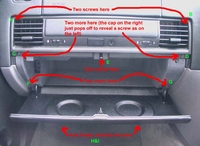
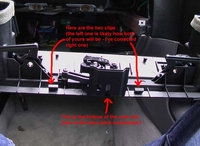
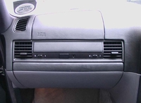
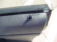
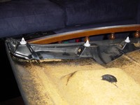
Anyway, first things first, let’s look at the glovebox as it is and locate the screws we need to remove:


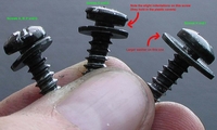
There are three different type of screws, together with E, which is a 10mm bolt (I think it was 10mm – can’t quite remember now). It is important to get the correct screws back in the correct places, otherwise the plastic caps over screws C and D will not go back on. The three screw types look like this:


I’d recommend removing screws H and I first of all, since it’s easier to do this with the glovebox door closed. They’re under the glovebox (you should be able to feel them – they’re more or less where screws F and G are, except beneath the actual glovebox, and a little way back).

Next, I’d take off screws A and B – they’re pretty easy to do, as long as you have a reasonably long, thin screwdriver. They are in the top left & right corners of the left & right passenger vents, respectively:


Then we can remove the vent assembly by taking off the plastic caps for screws C and D (in the picture above, screw D still has the plastic cap on) and then removing the screws beneath. The vent assembly should then just pull out; there are a couple of clips, but with a couple of seconds of patience, it comes off pretty easily. Then we’re left with the glovebox itself:


This is retained my the two remaining screws near the hinges and the bolt that is hidden under the interior light. In addition to these, there are two wires that supply power to the interior light and flashlight charger that need to be removed. First the interior light:


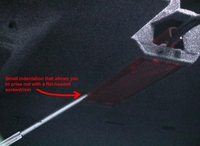
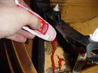
The interior light is very easy to remove when you find the indentation that is on the left edge, at the back of the light. Prise the light out with a flat bladed screwdriver. Be careful when removing the light itself now, and be sure to disconnect the power lines from the back. In the middle of the recess that held the interior light, there should be a 10mm (I think) bolt, which holds the glovebox onto the metal chassis supporting the airbag assembly. Locate this bolt with your fingers and then, using a wrench (I doubt you’ll be able to get to it using a spanner), unscrew the bolt.


Now we can remove the final two screws by the hinges, which can be removed with either an offset screwdriver or a long regular screwdriver:


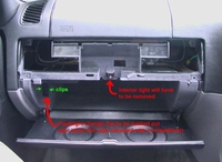
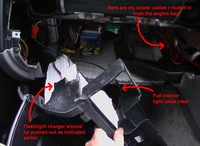
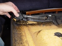
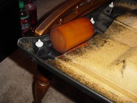
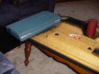
Now, the whole glovebox interior should begin to pull out. The only thing left to do is to pull the interior light clear and remove the flashlight charger. Press the clips indicated on the picture earlier with a flat-bladed screwdriver, and pull the back of the charger connector:


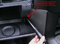
Now we have access to the electrics, should you wish to meddle. While we’re here, I can show you how to get to the mystical grommet that allows access to the engine bay (I routed some dedicated 20 Amp power lines for my Alpine head unit this way). Remove the horizontal kick panel just under the glovebox by pulling (it was secured by screws H and I, which we removed at the beginning of this process):


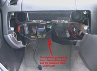
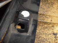
As you can see from the picture above, the access hole is beneath the carpet (not the mat, but the actual carpet – it just pulls back if you tug it hard enough) and under its attached heat-retardent foam. It is covered by a round plastic cover (which, incidentally is an exact fit over the cigarette lighter – I’ve now used that to make my car a no-smoking one!). This plastic cover just pulls off, revealing a hole. If you put your finger inside this hole you should feel a metal pipe running upwards (I think it was at about 270° to 315°). If you push a red (or other brightly coloured cable) up here, you should see it appear eventually in the engine bay. Note that if you want to run a black cable as well (and I can see the reason for only running one cable, personally), I’d recommend taping the end of the cables together and pushing them up together. This saves time, and the black cable is very hard to spot when it comes out in the engine bay. Power can then be routed from the fuse box connector (just under the lid of the box – held by a 12mm bolt, I think, and requires a 10mm ring connector on the red cable) and the chassis bolt near the air filter (8mm bolt I think, needing a 6mm ring connector on the black).


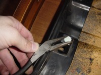
As for the other end of the power cables, this may be obvious advice, but I’d STRONGLY recommend using female connectors (bullets are perfect). The last thing you want is to use exposed males that end up touching and shorting out the fuse box!


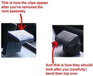
Once you’re done, the reassembly is a relatively easy task. However, in order to make sure your glovebox closes do not just reverse the order in which you did everything. The reason being is that the vent assembly (that clips on above the glovebox) has four plastic clips that will almost certainly not fully latch on to the glovebox interior.


First of all, if you’ve removed the horizontal kickpanel below the glovebox, reattach this (although do not screw it back in yet, since these screws also hold the bottom of the glovebox, which you have not put back yet). Now, take the vent assembly and turn it over so you’re looking at the back. You should see four clips, two small ones at the top of the assembly and two wider ones at the bottom. Chances are, the ones at the bottom have been bent outwards (away from the rest of the vent assembly) when you removed the plastic unit.


Carefully bend back the clip so that it forms an 80 or so degree angle (rather than the 100+ degree angle it was after removing the assembly). The picture below should make it clearer.


Once you’ve bent the bottom clips over, you’re ready to mount the vent assembly on to the glovebox interior (you need to do this before screwing the interior back in to make sure all four clips have taken). Now, reattach the combined glovebox interior and vent assembly into the hole (be careful to make sure the prongs at the bottom of the glovebox fit back inside the horizontal kickpanel piece). I then screwed back bolt E (into the hole left by the interior light), since on mine this required a bit of play in the glovebox to get the thing back into the hole. Then, it’s a simple matter of replacing all the remaining screws. Be careful when putting screws A and B back, as the screws can end up falling inside the vents. Make sure you close the vents first, and just take your time. If the vents are closed, you should be able to retrieve any dropped screws without having to remove the whole unit.


Finally, your reassembled glovebox should look as good as (or better than) new. Congratulations!


Are you looking for more do it yourself procedures (DIY) ? I recommend the Bentley BMW 3 series service manual for you. I got it and I think it’s a gold mine for us -BMW E36 Owners-. If you didn’t grab your copy yet, get it right now! I’m sure you’ll find this book worth every penny you’ve paid for. Get the Bentley BMW 3 series service manual


Wait for more from . . . BMW E36 Blog


Best regards,

Tony Sticks.

Want to receive exciting tips & information about BMW E36 cars? Enter your Email:-


posted in Do It Yourself, Interior, Technical Info | 7 Comments

31st March 2007

BMW On Board Computer (OBC) secrets!

Hi Friends,


I’m really excited about this new article and I think you will be excited too. I have found an article which describes the secrets hidden inside BMW E36 on board computer (OBC). It’s really fascinating me that the Germans in 1993 or so were having such things. All I can say is WOW!. OK, enough talking about the Germans, so Mr. OBC here turned to be not as simple as I really thought at first. It has many information that is hidden and can be displayed with tiny effort. I’m almost sure that you’re going to love the article below. I just wanted to say that you should make sure to try the Instrument Panel Tests. It’s really cool to watch your car checking itself.


Note: I did try almost all what’s written in here and it’s working great.


Disclaimer: Use this info at your own risk!! I’m not responsible for your mistakes man! 😀


There are many interesting functions available on the E36 OBC (On Board Computer) that are not documented in the owner’s manual, including changing the language of the display. The procedures described here work on my ’97 328iC, which has the upgraded OBC – they may work on other models of similar vintage.


Contents:

  • Programming the Display Order

  • Accessing Data

  • Unlock the Display

  • Test Codes

  • Setting the Country Code

  • Instrument Panel Tests


Programming the OBC to Display Contents in a Desired Order:


When you repeatedly press in on the turn signal stalk, the OBC display cycles through the various information types that it has in memory. The default sequence is: CONSUM1, CONSUM2, EXT. TEMP, SPEED, LIMIT, DIST and TIMER. If you want to change the display order, use the following procedure:
Press-in and hold the turn stalk for about 5 seconds. The OBC display will change to Prog 1. Press the button corresponding to the first function you would like to have displayed in the sequence. For example, if you would like the outside temperature to be displayed first, press the TEMP button. The display will then change to Prog2. Continue pressing the OBC buttons in the order you want, up through nine entries. You don’t have to enter all nine – if you would like the display to cycle only between TEMP and RANGE, simply enter those two items as Prog 1 and Prog 2. When finished, press the SET/RES button to store the sequence in memory.

To revert to the default order, simply press SET/RES as soon as Prog 1 is displayed.


Accessing Data in the OBC:

The OBC contains a lot of data, and displays the data in a manner determined by the country code that is stored in it. The technique to access this data is as follows:
Press the 1000 and 10 keys simultaneously. You should see Test-Nr.: appear in the display.
The table below lists the available test codes that are available. Enter a test code number, using the number keys, followed by the SET/RES key. However, to access codes other than 1, 10, 14, 19, and 21,
you have to first unlock the OBC, using the procedure described below.
Read the results.
For test numbers 10 and 11, enter a new value (if desired) and press SET/RES.
Return to the normal display functions by pressing CHECK or any other key.
 
Unlock the Display:

Most of the test sequences require you to first unlock the display before. Enter test code 19 using the above procedure. The display should read LOCK:ON. Then enter an unlocking code consisting of the sum of the current month plus date (for example, if today is July 11, enter 18). Then press SET/RES, and the OBC is now unlocked.
 

Test Codes:

Following is a listing of the available tests, along with with my notes as to what I think each test means. Note that the display uses European conventions for decimals (i.e., the number 61,7 is 61.7f or us Americans). You will see that I don’t have good explanations for several of these test codes


Test Code No.

Display

Notes

Display Must Be Unlocked First?

01

All LED display elements are lit

Verify that the display is working properly

No

02

VBR: n,n l/100km

n,n = instantaneous fuel usage in liters/100 km

Yes

03

VBR: n,n l/h

n,n = instantaneous fuel usage in liters per hour

Yes

04

RW-VBR: n,n l/100

n,n = average fuel usage in liter/100 km.

Yes

05

RW: nnn km

nnn = range in km

Yes

06

Not used

Yes

07

TMTL: nn,n l

nn,n = fuel remaining (in liters)

Yes

08

V: n km/h

n = instantaneous speed in km/h

Yes

09

UB: nn,nn V

nn,nn = system voltage (should be
around 13,80)

Yes

10

LAND: n xxx *

Country code — for US drivers
should be set to 2 USA — see description below

No

11

EINHEIT n: xx *

?? There are two EINHEIT displays: the values for xx in EINHEIT 1 can range between B0 and BF, and for EINHEIT 2 range between 0F and FF (mine is set to B3 and FF, respectively). Press the 1000 or 100 key to switch between EINHEIT 1 and EINHEIT 2.

Yes

12

VANK nn km/h

nn = average speed

Yes

13

ANK: nn:nn

nn:nn = ETA (will display
–:–
if the OBC’s distance function is not in use)

Yes

14

ROM: dd.mm.yy

dd.mm.yyyy = Software version date. Mine is 25.06.1991

No

15

DIAG: nn nn nnn xx

Diagnosis code? Mine is 01 05 255 FA

Yes

16

PORT: nn nnnnnnnn

Port codes? Press 1000
or 100 key to cycle port numbers. For example, PORT 01 is 10101000

Yes

17

PROM: nn nn

?? Mine reads 00 12

Yes

18

HORN: xxxx

DTON or DTOFF?
(Single tone horn versus dual tone)

Yes

19

LOCK: xx

xx = ON or OFF.
See description above for method.

No

20

KVBR: nnnn

nnnn = Fuel rate calibration factor. Mine is set to 1000

Yes

21

RESET?

Reset all defect codes? Also erases all stored values in the OBC (i.e, fuel consumption, avg. speed, timer, etc) and clock.

Yes


Note: #20 The factor is used to correct the OBC Avg Fuel Consumption figure to reality. If your OBC is off a bit, fill it UP totally and then run the tank down and refill. Then calculate your Actual MPG. Now enter test #20 get the old Correction Factor. NEW CF = OLD CF *(Actual MPG/OBC MPG)

Setting the Country Code:

If your OBC suddenly starts displaying every thing in German, and you would like to put it back to English, use test sequence number 10. Once you’re into test number 10, press the 1 key several times, and you’ll see the display cycle through various country options. For example, 0 is for Germany (the display reads LAND:0 D * – I assume D stands for Deutschland). As you cycle through the options, you’ll see choices for the Great Britain, USA, France, Canada, etc. Once the display is on the country you want, press the SET/RES key to store your choice into memory — for US drivers the display should be set to LAND: 2 USA * . Then press the CHECK key, and the display will reflect the units of the country you’ve chosen.

Instrument Panel Tests:

With the engine off, press and hold the trip mileage reset button, and then turn the key to accessory position 2 (OBC and radio come on). The LED display on the instrument panel (which normally is the odometer) will change to tESt01 and then will begin to cycle through several displays. Release the button. The display will continue to cycle through several displays. Here’s the data my car displays:


Display

Display Sequence

Notes


363758


1

BMW Part No.


0000


2

Code No.?


7504


3

K No.?


nnnnn


4


Last 5 digits of VIN


230


5

Software Version


62


6

Revision Index Hardware No.


Finally, all LED elements will light, and all gauges will cycle once.
You can press the mileage-reset button again to access more tests. Tests 2 through4 are always unlocked and hence available. Tests 5 through 14 are normally locked — to access these you must first unlock the display-using test 15.Otherwise the display simply shows: ——–.


Display

Test Sequence

Notes

n

02

Engine type: n = 2 for 4-cylinder engine, 3 for 6-cylinder, and 4 for 8-cylinder

nnnnnn

03

km traveled since last oil service reset.

nnnn

04

Age of car, in days

For tests 5 – 13, display must first be unlocked using sequence 15.

n

05

SI evaluation factor: n = 0 or 1 (over-rev), t= 0 or 1 (engine temp over heat)


06

Fuel level and coolant temp. Displays hexadec codes relating to gauge position:

Fuel Gauge Hex value:
A (empty) —-> 0d
End of Reserve —-> 37
B ——> 54
C ——–> 90
D ———> c4
E (full) ——> f0

Engine Temp Hex value:
A ——-> ce
B ——–> 6d
C ——–> 5c
D (center) ——> 4f-23
E ——–> 1e
F ———> 18


07

Current engine RPM


08

Current road speed in km/h

nnnnnn A

09

Distance – used to compare odometer mileage in the EPROM vs. the coding plug. If the two values don’t agree (for example, if one of these elements was replaced), the manipulation dot will illuminate. This function will synchronize the two readings to the highest value. Press and hold the reset button for 4 seconds, and the lower mileage reading will be overwritten by the higher, and the manipulation dot is cancelled.

bbbbbb

10

Status bits – input signal (0=low
or 1= high):
1: seat belt: fastened =0
2: ignition lock: key inserted=0
3: door contact: door open = 0
4: clock button pressed = 0
5: SI reset = 0
6: EGS transmission failure = 0

bbbbbb

11

Status bits – output signals:
1: Gond output
2: Brake warning lamp
3: Low fuel warning lamp
4: EGA lamp
5: Seat belt lamp
6: manipulation dot

——

12

Not used

nn

13

Country code of cluster (USA = 02)


14

Software reset

L On/Off

15

Lock Status (on or off). Press and hold the reset button for about five seconds until the display reads "OFF". Now you can access test sequences 5 through 14.


Wait for more from . . . BMW E36 Blog


Best regards,

Tony Sticks.

Want to receive exciting tips & information about BMW E36 cars? Enter your Email:-


posted in Interior, Technical Info, Tips & Tricks | 134 Comments

28th March 2007

Fixing BMW E36 door panel!

Hi Friends,


The door panels in BMW E36 and especially the coupe type is a very common problem that every owner will sooner or later face. As you might have guessed I’m facing this problem right now with my babe :-(. So it’s time to fix it, but I realized that I don’t have any knowledge about the issue, so how am I supposed to fix it. Well, as usual, I will go out and dig to find some people who faced this problem before me and successfully solved it. I’ve found this post which describes the process in detail and I thought I should share it with you guys. Maybe you’d like to do the same to your cars.


Note: don’t forget to buy some clips before starting the surgery, otherwise you will fail to do the job successfully. Good luck!


Disclaimer: Use this procedure at your own risk!! I’m not responsible for your mistakes man! 😀


This is a simple way to fix you sagging or lose door card. I spent about 10 min doing everything, the only catch is that you will need to let the
adhesive cure or dry.


Removal: The panel is fastened by clips and screws, there are 2 screws tucked behind the handle on the arm rest, simply pop the covers off and unscrew them, after that just pull the door card off and unplug the speakers, the speaker wires pull right out, don’t be to
aggressive though as you may damage them.


Things you’ll need once the door panel is off:

Pliers, and RTV silicone.


This is what it looked like before I took it off the car


This is what the repair did


Once I examined the door I found what the cause was. There is a plastic molding holding the door clips that was glued to the door card and had separated itself due to many opening and closings.


Some of the clips were broken as well. I recommend purchasing new ones from the dealer, don’t be a cheap wad. You should have these clips before the repair so that you can do everything at once. To remove the clips simply wist and pull them with pliers, they are notched and are designed to be done that way.


Remove the clips before you decide to apply the adhesive as this may cause some issues later on in the repair. To put new clips in, just twist them in with your fingers, it doesn’t take much effort.


Next you simply apply the adhesive thoroughly. Cleaning shouldn’t really be an issue, but if you decide to clean the area, use a mild soap and warm water. Push down on the plastic to spread the silicone around, you don’t need to smooth it, let the plastic do the work for you, plus you don’t get dirty.


That’s pretty much it for the repair, the next thing you’ll want to do is apply pressure. I chose to use a piece of cylinder poly and laid my amp on it. You’ll want to have adequate pressure to ensure a tight bond. When you add the weight, have the door panel somewhere that will be out of ways harm. I chose the coffee table….


Let the RTV dry before you mount it back on the car. I let mine sit over night just to be safe. Simply reverse the removal process to re-attach the door panel…and your finished


Hope this helps, it’s super easy and cheap, it’s not the most interesting thing in the world but I needed it fixed so I’m sure someone else does to. If you guys think I left something out then let me know but I think I covered everything.


Are you looking for more do it yourself procedures (DIY) ? I recommend the Bentley BMW 3 series service manual for you. I got it and I think it’s a gold mine for us -BMW E36 Owners-. If you didn’t grab your copy yet, get it right now! I’m sure you’ll find this book worth every penny you’ve paid for. Get the Bentley BMW 3 series service manual


Wait for more from . . . BMW E36 Blog


Best regards,

Tony Sticks.

Want to receive exciting tips & information about BMW E36 cars? Enter your Email:-


posted in Do It Yourself, Interior, Technical Info, Tips & Tricks | 14 Comments

25th March 2007

A great tip for BMW owners!

Hello guys,


Yesterday, I was cleaning my car interior when I noticed a very nice option in my car that I didn’t know about it before in E36s. But because I was cleaning and very busy with it, I couldn’t check it until today. This morning, I sit behind my wheel and tried it and it was really fantastic. Did you want to know what I’ve found? Did I have you attention? LOOOL! ok, cut the crap, I will let you know what I’ve found.


Have you ever noticed that the turn signal stick behind your wheel has an arrow drawn on it with a BC text on it? If not, then I think you should sit behind your car wheel and try to see it. If you see that, then press the turn signal stick and you’ll notice that it’s clicking. What do you think this click do? It controls the OBD (On Board Computer). Every time you click on it, it will move to the next option and display it on the screen of your OBD. If you didn’t understand the procedure, I prepared some photos for you.


Hmmm… nice find isn’t it. I hope you liked it as much as I did. OK bye for now and I
will be BACK.


Wait for more from BMW E36 Blog.


best regards,

Tony Sticks.

Want to receive exciting tips & information about BMW E36 cars? Enter your Email:-


posted in Interior, Tips & Tricks | 4 Comments

15th February 2007

Illuminating BMW E36 M3 logo!

Hi Guys,


Today, I came to you with a very nice touch that you absolutely need to do to your M3 BMW. In the following procedure (which was originally written by barefootshifter (bimmerforums) . Thanks to him) you can illuminate your M3 (M///) logo that you have between the speed & rpm gauges. I have to admit that the procedure is a little bit difficult, but the result is fabulous. If you’re not convinced you need to do this work, just take a look at the end of the article with photos of the M3 logo after the job is done. I really like this, so … enjoy my friends…


Disclaimer: Use this procedure at your own risk!!


Ok I recently posted pics of my illuminated M logo; here’s how to create your own.


Step 1 Remove screws holding in gauge cluster. They are #20 torx head and are located here.


STEP 2 Pry out cluster using something flat and skinny–I used a putty knife. Be VERY careful as you don’t want to scratch the dash or gauge cluster!


Step 3 Pull the cluster towards you (the steering wheel should be in its normal position.)


Step 4 Unclip the 3 wiring harnesses in the back of the cluster. This gets a little tricky because the way the harness works. It has a clasp that locks in a down position and you have to depress the spot right in front of it in order to slide it up. I have pointed to the spot you need to press.


Read the rest of this entry »

Want to receive exciting tips & information about BMW E36 cars? Enter your Email:-


posted in Do It Yourself, Interior, Tips & Tricks | 1 Comment